|
| |
TM 9-2320-364-34-2
9-106
This task covers:
a. Removal
c. Assembly
e. Follow-On Maintenance
b. Disassembly
d. Installation
INITIAL SETUP
Materials/Parts
Sealing Compound (Item 60, Appendix B)
Equipment Condition
Engine shut OFF, (TM 9-2320-364-10)
Wheels chocked, (TM 9-2320-364-10)
Brake assembly removed, (Para 10-2)
Axle air lines removed, (TM 9-2320-364-20)
Tools and Special Tools
Tool Kit, General Mechanic’s
(Item 240, Appendix F)
Gloves, Heavy Duty (Item 82, Appendix F)
Press, 60 Ton (Item 164, Appendix F)
Puller Kit, Universal (Item 174, Appendix F)
Socket, Socket Head Screw, 12 mm
(Item 206, Appendix F)
Torch, Propane (Item 247, Appendix F)
Wrench, Torque (0-175 lb-ft [0-237 N.m])
(Item 277, Appendix F)
9-14. AXLE NO. 3 AND 4 SPINDLE ASSEMBLY REPAIR.
a.
Removal.
Spindle is heavy. Properly support spindle during disassembly or serious injury to
personnel may occur.
NOTE
It may be necessary to tap spindle with soft faced mallet to break adhesive grip.
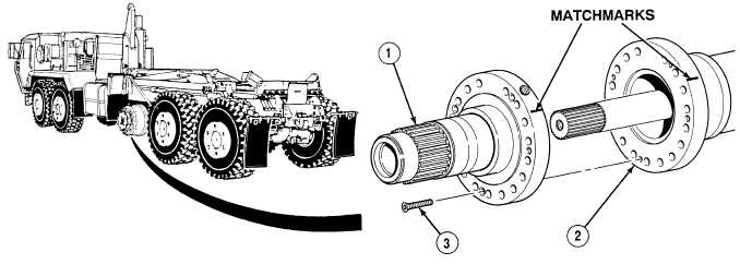
Axle No. 3 and 4 spindles are replaced the same way.
Axle No. 3 spindle is shown.
(1)
Matchmark spindle (1) and Axle No. 3 housing (2).
(2)
Remove two screws (3) and spindle (1) from Axle No. 3 housing (2).
|