|
| |
TM 9-2320-364-34-3
14-65/(14-66 blank)
NOTE
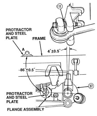
Frame must be level to perform axle camber adjustment properly.
Axle camber angle measurements must be taken with relationship to frame. If frame is not
level, the angle the frame is inclined must be added or subtracted from flange assembly
measurement.
Axle flange measurement of 86 0.5 degrees equals axle camber of four degrees 0.5 (90
degrees – 86 degrees = four degrees).
(c)
Measure the angle (in degrees) that
flange assembly is cambered.
1
Position protractor and steel plate
on frame at point A. Adjust
protractor to zero.
2
Position protractor and steel plate
on machined surface of the flange
assembly and record measurement.
This is point B. Measurement
should read 86 degrees 0.5 degrees
(d)
If axle camber is not four degrees 0.5
degrees, add or subtract spacers (11)
until correct axle camber is achieved.
f.
Follow-On Maintenance:
LHS in transit position, (TM 9-2320-364-10) (Axles No. 3 and No. 4 only).
Install rear hardlift assembly, (TM 9-2320-364-20) (Axle No. 5 only).
Install driveshafts, (TM 9-2320-364-20).
Remove wheel chocks, (TM 9-2320-364-10).
END OF TASK
|