|
| |
TM 9-2320-364-34-4
20-84
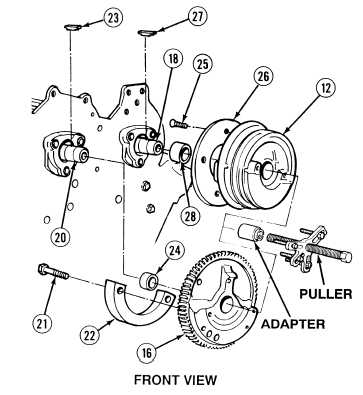
20-34. CAMSHAFT ASSEMBLY REMOVAL (CONT).
(11)
Using mechanical puller and adapter,
remove water pump drive gear (16) from
right camshaft (20).
(12)
Remove two lockscrews (21) and balance
weight (22) from water pump drive
gear (16). Discard lockscrews.
(13)
Remove key (23) and spacer (24) from front
end of right camshaft (20). Discard key.
(14)
Using mechanical puller and adapter,
remove camshaft front balance pulley (12)
from left camshaft (18).
(15)
Remove four screws (25) and speed sensor
wheel (26) from front balance pulley (12).
(16)
Remove key (27) and spacer (28) from front
end of left camshaft (18). Discard key.
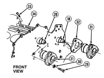
(17)
Remove three screws (29) and
lockwashers (30) from two bearings (31).
Discard lockwashers.
NOTE
Gasket is on left hand bearing
only.
(18)
Remove two bearings (31) and gasket (32)
from right camshaft (20) and left
camshaft (18). Discard gasket.
(19)
Remove six intermediate bearing
setscrews (33) from engine block (34).
Discard setscrews.
|