|
| |
TM 9-2320-364-34-4
20-182
20-60. PISTON AND CONNECTING ROD REPAIR (CONT).
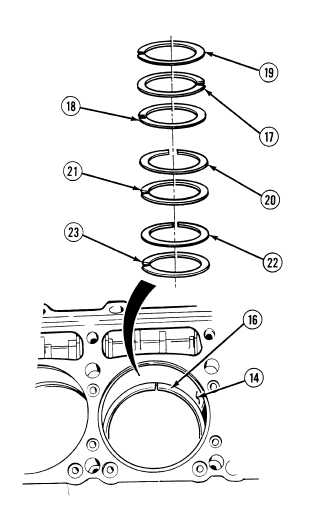
NOTE
Fire ring has two
identification marks, top
compression ring has no
identification marks, and
bottom compression ring
has no marks. Upper oil
control rings have orange
stripe and lower oil control
rings are black rings.
Use piston skirt to position
ring parallel with top of
cylinder liner.
(26)
Insert and measure piston rings (16) one at a
time inside cylinder liner (14) far enough to
be in area of ring travel 2.0 to 3.0 in.
(5.1 to 7.6 cm) deep.
(27)
Top compression ring (17), bottom
compression ring (18) and fire ring (19)
must have minimum gap of 0.0250 in.
(0.6350 mm) and maximum gap of 0.0600 in.
(1.524 mm).
(28)
Upper oil control rings (20) and (21) must
have gap between minimum of 0.0070 in.
(0.1778 mm) and maximum of 0.0350 in.
(0.8890 mm).
(29)
Lower oil control rings (22) and (23) must
have gap between minimum of 0.0100 in.
(0.2540 mm) and maximum of 0.0430 in.
(1.0922 mm).
(30)
If any rings are below minimum clearance,
replace rings.
(31)
Replace all parts failing inspection.
|