|
| |
TM 9-2320-364-34-4
20-243
Materials/Parts
Oil, Lubricating (Item 36, Appendix B)
Lockscrew (8) (Item 222, Appendix E)
Packing, Preformed (Item 358, Appendix E)
Pin, Dowel (2) (Item 430, Appendix E)
This task covers:
a. Installation
b. Follow-On Maintenance
INITIAL SETUP
Equipment Condition
Crankshaft front cover and seal installed,
(Para 20-68)
Tools and Special Tools
Tool Kit, General Mechanic’s
(Item 240, Appendix F)
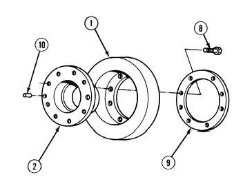
20-69. VIBRATION DAMPER INSTALLATION.
a.
Installation.
NOTE
If removed install two dowels.
(1)
Install two dowels (10) in unthreaded bores
of hub assembly (2).
(2)
Press two dowels (10) through hub
assembly (2) until dowels stick out from hub
3/8 in. (9.5 mm).
(3)
Install scuff plate (9) and hub assembly (2)
in vibration damper (1) with eight
lockscrews (8).
(4)
Tighten eight lockscrews (8) 75 to 85 lb-ft
(102 to 115 N.m).
|