|
| |
TM 9-2320-364-34-4
21-13
(14)
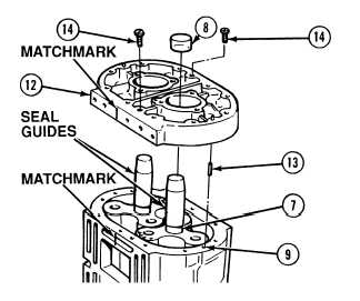
Install seal guides on gear end of rotor
shaft (7).
NOTE
Plastic inserts in seal will come
out with installation of rear end
plate.
(15)
Align matchmarks and position rear end
plate (12), machined side down, and align
dowel pins (13) to holes in blower
housing (9).
(16)
Using soft faced hammer, tap rear end
plate (12) in blower housing (9) to remove
plastic inserts (8). Discard plastic inserts.
(17)
Install and tighten two screws (14) in rear end
plate (12) to 60 to 120 lb-in (7 to 14 N.m).
NOTE
Perform Step (18) for rear
and front end plate.
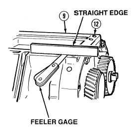
Two measurements are
taken on each end plate.
Each measurement should
be taken one in. (25 mm)
from each end of end plate.
Protrusion of blower
housing to end plates should
not be more than 0.0005 in.
(0.01270 mm) above to
0.0065 in. (0.1651 mm)
below end plate.
Protrusion in Step (18) is
checked at cylinder block
side of blower.
(18)
Using feeler gage and straight edge, check
blower end plate (12) to blower housing (9).
|