|
| |
TM 9-2320-364-34-4
21-34
21-3. TURBOCHARGER ASSEMBLY REPAIR (CONT).
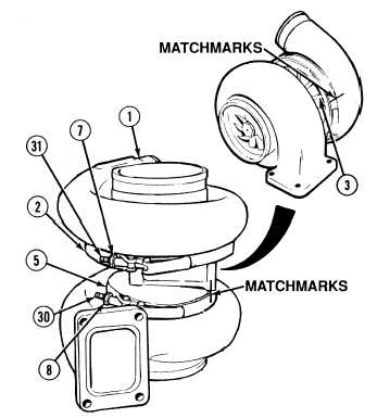
(35)
Loosen locknut (8) on clamp (5) and
retighten to 50 lb-in (6 N.m).
(36)
Tighten locknut (8) on clamp (5) to 165
lb-in (18.9 N.m).
(37)
Install clamp (2) over center housing (6).
(38)
Align matchmarks on turbo housing (1) and
backplate (3) and install turbo housing (1)
on backplate (3).
(39)
Apply lubricating oil to threads of
screw (31).
(40)
Tighten locknut (7) on screw (31) to 110 to
130 lb-in (12 to 15 N.m).
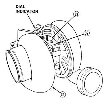
(41)
Position dial indicator with magnetic base
swivel adapter and extension rod, on flat
surface of housing inlet flange (32).
NOTE
Do not allow extension rod to
touch sides of center housing.
Inaccurate readings can result in
poor fit and damage.
(42)
Position extension rod in oil drain hole (33)
so rod is against turbine wheel shaft.
NOTE
Disassemble and inspect
turbocharger if fit of turbine
wheel shaft is not within limits.
(43)
Ensure turbine wheel shaft moves up and
down not more than 0.0070 in. (0.177 mm)
or less than 0.003 in. (0.076 mm).
END OF TASK
|