|
| |
TM 9-2320-364-34-4
23-12
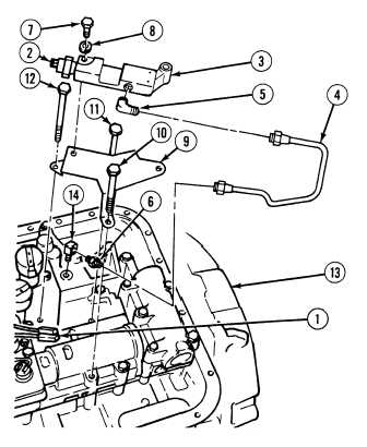
23-5. TRANSMISSION LOW OIL SENSOR ASSEMBLY REPLACEMENT (CONT).
b.
Installation.
NOTE
Install fittings in position noted
prior to removal.
(1)
Install elbow (5) in low oil sensor body (3).
(2)
Install elbow (14) in transmission (13).
(3)
Install fitting (6) on elbow (14).
(4)
Install bracket (9) to transmission (13) with
screws (10), (11) and (12).
(5)
Position low oil sensor body (3) on
bracket (9) with two washers (8) and
screws (7).
(6)
Install oil pressure switch (2) to low oil
sensor body (3).
All valve body screws should be
started by hand to prevent
binding. Tighten all screws to 50
percent of specified torque.
Repeat tightening sequence to
100 percent torque.
NOTE
If screw binds during installation,
loosen all screws and check
alignment of control valve and
components. Repeat tightening
procedure until all screws can be
tightened without binding.
(7)
Tighten screws (7), (10), (11) and (12) finger tight.
(8)
Tighten screws (7), (10), (11) and (12) to 8 to 12 lb-ft (11 to 16 N.m).
(9)
Install low oil sensor tube assembly (4) on fitting (6) and elbow (5).
(10)
Install two electrical connectors (1) on oil pressure switch (2).
c.
Follow-On Maintenance:
Install internal oil filter, (Para 23-4).
END OF TASK
|