|
| |
TM 9-2320-364-34-4
23-33
(6)
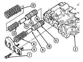
Install fourth clutch trimmer valve (11),
shorter land first, plug (10), spring (8) and
valve stop (9) in control valve body (2).
(7)
Install second clutch trimmer valve (16),
shorter land first, plug (15), spring (13),
spring (12) and valve stop (14) in control
valve body (2).
NOTE
Springs must be compressed to
properly install trimmer valve
cover.
(8)
Install trimmer valve cover (6) on control
valve body (2) with eight screws (7). Tighten
screws to 96 to 144 lb-in (11 to 16 N.m).
NOTE
Make sure trim boost regulator
valve spring is solid light blue
and end color is light green.
(9)
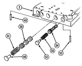
Install trim boost regulator valve (54),
spring (55) and valve stop (52) in control
valve body (2).
(10)
Compress spring (55) and install retaining
pin (53).
(11)
Position control valve body (2) flat side up
on clean work surface.
NOTE
Make sure 4-5 shift valve spring
is solid blue with yellow stripe.
(12)
Install 4-5 shift valve (50), spring (51) and
valve stop (48) in control valve body (2).
NOTE
Flared end of pin must extend
0.065 to 0.069 in. (1.651 to
1.753 mm) above surface of
valve body with opening of flare
pointing in.
(13)
Compress spring (51) and install flared
spring pin (49) in control valve body (2).
|