|
| |
TM 9-2320-364-34-4
25-2
This task covers:
a. Installation
b. Removal
c. Follow-On Maintenance
INITIAL SETUP
Equipment Condition
Axle removed from truck,
(Para 9-3, Para 9-4, Para 9-11,
Para 9-12 or Para 9-13)
Tools and Special Tools
Tool Kit, General Mechanic’s
(Item 240, Appendix F)
Stand, Maintenance, Axle (Item 225, Appendix F)
Lifting Device, Minimum Capacity 2200 lbs
(999 kg)
25-2. AXLE ON STAND REMOVAL/INSTALLATION.
a.
Installation.
Axle No. 3 weighs 2,048 lbs
(930 kg). Attach a suitable
lifting device prior to removal to
prevent possible injury to
personnel. Stabilizing chains
must be attached to axle housing
to prevent an out of balance
condition when axle is lifted.
Axle could roll out of control
causing serious injury or death
to personnel.
NOTE
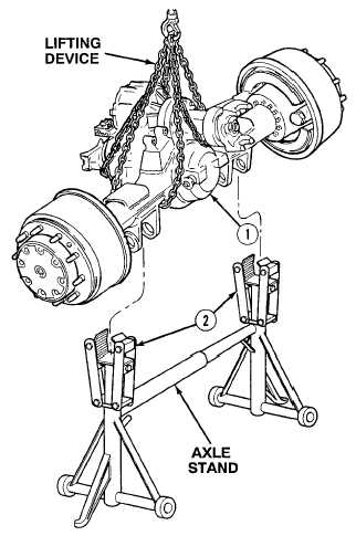
Axle No. 3 is shown. Axles No. 1,
2, 4 and 5 are similar.
(1)
Attach lifting device to Axle No. 3 (1).
(2)
Position Axle No. 3 (1) on axle stand and
tighten two axle stand clamping bolts (2).
(3)
Remove lifting device from Axle No. 3 (1).
|