|
| |
TM 9-2320-364-34-4
25-4
Materials/Parts
Compound, Antiseize (Item 14, Appendix B)
Oil, Lubricating (Item 36, Appendix B)
This task covers:
a. Caging Air Brake Chamber
c. Installation
e. Follow-On Maintenance
b. Removal
d. Uncaging Air Brake Chamber
INITIAL SETUP
Personnel Required
Two
Equipment Condition
Axle on stand, (Para 25-2)
Tools and Special Tools
Tool Kit, General Mechanic’s
(Item 240, Appendix F)
Wrench, Torque (0 to 175 lb-ft [0-237 N.m])
(Item 277, Appendix F)
Lifting Device, Minimum Capacity 132 lbs
(60 kg)
25-3. AXLE NO. 1, 2 AND 5 BRAKE DRUM REPLACEMENT.
Materials/Parts - Continued
Sealing Compound (Item 53, Appendix B)
Packing, Preformed (Item 399, Appendix E)
a.
Caging air brake chamber.
NOTE
Only Axles No. 3, 4, and 5 are caged.
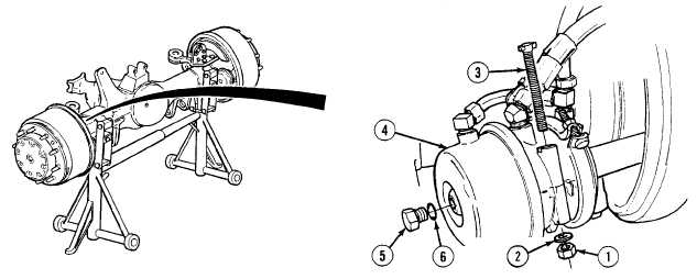
Perform Steps (1) through (4) for Axle No. 5. Axle No. 5 is shown.
(1)
Remove nut (1), washer (2) and caging bolt (3) from storage slot of air brake chamber (4).
(2)
Remove plug (5) and preformed packing (6) from air brake chamber (4). Discard preformed packing.
|