|
| |
TM 9-2320-364-34-4
25-44
25-12. AXLE NO. 1, 2 AND 5 PIVOT AND SPINDLE/TRUNNION BEARING
ASSEMBLY REPAIR (CONT).
a.
Removal.
NOTE
Tag and mark all parts to
prevent interchanging
during installation.
Pivot and spindle assembly
on left side of truck has
steering arm. Pivot and
spindle assembly on right
side of truck has upper
cover.
Procedures for spindles are
the same. Axle No. 1 left
side is shown.
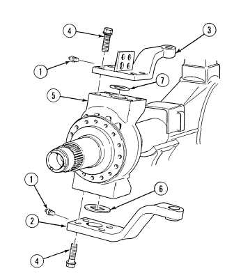
(1)
Remove two grease fittings (1) from
steering swivel arm (2) and upper cover (3).
(2)
Remove four screws (4) and steering swivel
arm (2) from pivot and spindle assembly (5).
(3)
Remove shim (6) from pivot and spindle
assembly (5). Discard shim.
(4)
Remove four screws (4) and upper cover (3)
from pivot and spindle assembly (5).
(5)
Remove shim (7) from pivot and spindle
assembly (5). Discard shim.
|