|
| |
TM 9-2320-364-34-4
25-52
Materials/Parts
Grease (Item 22, Appendix B)
Solvent, Drycleaning (Item 68, Appendix B)
Wire, Nonelectrical (Item 79, Appendix B)
Cross (2) (Item 38, Appendix E)
Fitting, Grease (4) (Item 50, Appendix E)
Sealing Kit (Item 623, Appendix E)
This task covers:
a. Removal
c. Installation
b. Cleaning/Inspection
d. Follow-On Maintenance
INITIAL SETUP
Personnel Required
Two
Equipment Condition
Axle No. 1, 2 and 5 pivot and spindle/trunnion
bearing assembly removed, (Para 25-12)
Tools and Special Tools
Tool Kit, General Mechanic’s
(Item 240, Appendix F)
Extractor, Inertial (Item 56, Appendix F)
Extractor, Inertial (Item 57, Appendix F)
Gloves, Chemical Oil Protective
(Item 81, Appendix F)
Goggles, Industrial (Item 83, Appendix F)
Pliers, Retaining Ring (Item 158, Appendix F)
Press, 60 Ton (Item 164, Appendix F)
Puller Kit, Universal, Slide Hammer
(Item 175, Appendix F)
Removal Tool, Bearing Cap, Constant Velocity
U-Joint (Appendix C)
25-13. AXLE NO. 1, 2 AND 5 CONSTANT VELOCITY JOINT REPAIR.
a.
Removal.
The following step keeps clutch gear from disengaging after constant velocity shaft are
removed. Failure to perform step makes assembly difficult and could damage parts.
NOTE
Screw used in Step (1) is from locking cylinder.
Step (1) is for left side constant velocity joint removal on Axle No. 1 and 5 only.
Step (1) is for right side constant velocity joint for Axle No. 2 only.
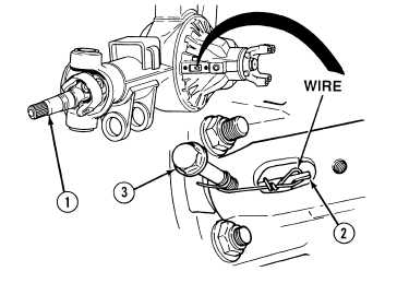
Axle No. 1 is shown in illustration. Axles No. 2 and 5 are similar.
Axles No. 1, 2 and 5 constant
velocity shafts are removed the
same.
Clutch collar is engaged when
both constant velocity shafts turn
in the same direction when axle
yoke is turned.
(1)
With the aid of an assistant, engage clutch
collar by turning constant velocity shafts (1)
slowly, while pulling outward on fork (2).
(2)
Form a wire hook around fingers of fork (2)
and anchor with screw (3).
|