|
| |
TM 9-2320-364-34-4
25-72
25-15. AXLE NO. 1 AND 5 DIFFERENTIAL ASSEMBLY REPAIR (CONT).
NOTE
Perform Step (30) only if
locating pins were removed.
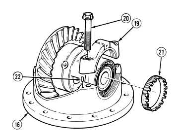
(32)
Install four locating pins (22) in differential
housing (16).
(33)
Install adjusting nut (21), two bearing
caps (19) and four screws (20) in differential
housing (16). Tighten screws to 25 lb-in
(3 N.m).
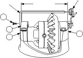
(34)
Install differential preload adapter on
bearing cap (19) with screw (17).
(35)
Position dial indicator base on bearing
cap (19) and indicator end on differential
preload adapter.
NOTE
Steps (36) through (38) adjust
bearing preload of differential
and bevel gear.
(36)
Tighten adjusting nut (21) to obtain a dial
indicator measurement of 0.0137 to 0.017 in.
(0.3480 to 0.432 mm).
(37)
Remove dial indicator, screw (17) and
differential preload adapter from bearing
caps (19).
DIFFERENTIAL
PRELOAD
ADAPTER
DIAL
INDICATOR
DISTANCE
BETWEEN
BEARING CAPS
19
19
17
21
|