 |
|||
|
|
|||
|
Page Title:
BLACKOUT STOPLIGHT(S) DO NOT OPERATE (S/N YB6122 075 AND UP). (Cont) |
|
||
| ||||||||||
|
|
 TM 9-2330-385-14
Remove all jewelry such as rings, dog tags, bracelets, etc. If jewelry or tools contact positive electrical
circuits, a direct short may result. Damage to equipment, injury, or death to personnel may occur.
VOLTAGE TEST
(1) Set multimeter select switch to
volts dc.
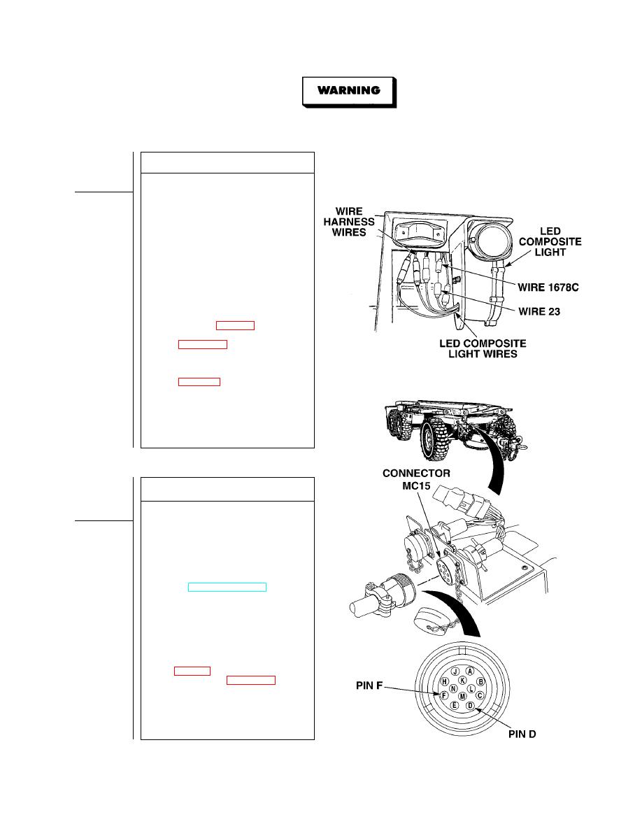
(1.1)Disconnect wire 1678C/23 from
nonoperating LED composite light.
(2) Connect positive (+) multimeter lead
to wire 1678C.
(3) Connect negative (--) multimeter lead
to a known good ground.
(4) Turn on BLACKOUT LIGHTS selector
switch.
(5) While assistant fully applies brake
pedal, observe blackout stoplights.
(a) If 22 to 28 vdc are not present,
perform Steps (6) and (7) below
and repair wire 1678C/23 (see
schematic, Fig FO-1.1) or replace
composite light wire harness
(b) If 22 to 28 vdc are present, perform
Steps (6) and (7) below and replace
LED composite light
(6) Release brake pedal.
(7) Turn off BLACKOUT LIGHTS selector
switch.
(8) Connect wire 1678C/23.
VOLTAGE TEST
(1) Disconnect 24 vdc (12 pin) cable from
front junction box connector MC15.
(2) Set multimeter select switch to volts DC.
(3) Connect positive (+) multimeter lead
to pin F on trailer end connector.
(4) Connect negative (--) multimeter lead
to pin D on trailer end connector.
(5) Turn on BLACKOUT LIGHTS selector
switch (TM 9-2320-364-10).
(6) While assistant fully applies brake
pedal, observe multimeter.
(a) If 22 to 28 vdc are not present,
perform Steps (7) and (8) below
and replace 24 vdc cable.
(b) If 22 to 28 vdc are present, perform
Steps (7) through (9) below and
repair wire 1678C (see schematic,
wire harness (Para 4-30.1)
(7) Release brake pedal.
(8) Turn off BLACKOUT LIGHTS selector
switch.
(9) Connect 24 vdc cable to front junction
box connector MC15.
|
|
Privacy Statement - Press Release - Copyright Information. - Contact Us |
