 |
|||
|
|
|||
|
Page Title:
FRONT SIDE MARKER LIGHT DOES NOT OPERATE. (Cont) |
|
||
| ||||||||||
|
|
 TM 9-2330-385-14
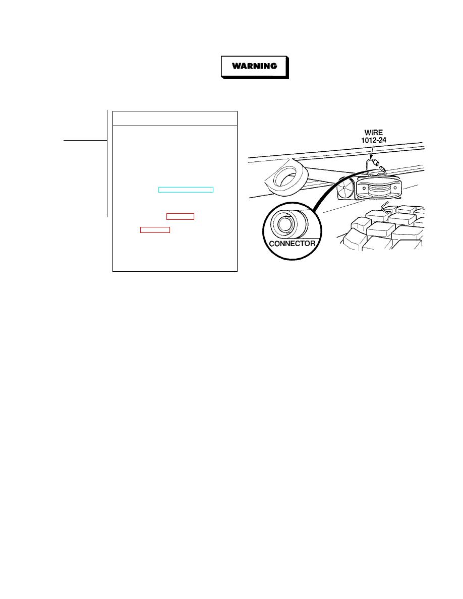
Remove all jewelry such as rings, dog tags, bracelets, etc. If jewelry or tools contact positive electrical circuits,
a direct short may result. Damage to equipment, injury, or death to personnel may occur.
VOLTAGE TEST
(1) Set multimeter select switch to
volts dc.
(2) Connect positive (+) multimeter lead
to wire 1012-24 connector.
(3) Connect negative (- ) multimeter lead
-
to a known good ground.
(4) While assistant turns ON ENGINE
switch and turns on lights, observe
multimeter (TM 9-2320-364-10).
(a) If 10 to 14 vdc is not present,
perform Steps (5) and (6) below,
and repair wire 1012-24 (see
schematic, Fig FO-1) or replace
left front side marker harness
(b) If 10 to 14 vdc is present, wire
1012-24 is OK.
(5) Turn off lights.
(6) Turn OFF ENGINE switch.
(7) Connect wire 1012-24 connector.
|
|
Privacy Statement - Press Release - Copyright Information. - Contact Us |
