 |
|||
|
|
|||
|
Page Title:
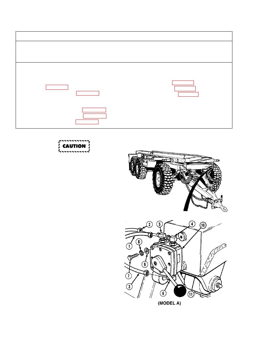
DRAWBAR AIR ASSIST CONTROL REPLACEMENT. |
|
||
| ||||||||||
|
|
 TM 9-2330-385-14
This task covers:
a. Removal
b. Installation
c. Follow-On Maintenance
INITIAL SETUP
Tools and Special Tools
Equipment Condition
Tool Kit, General Mechanic's: Automotive
Wheels chocked, (Para 2-20)
(Item 50, Appendix J)
Drawbar lowered, (Para 2-23)
Cap and Plug Set (Item 2, Appendix J)
Air system drained, (Para 2-21)
Materials/Parts
Sealing Compound (Item 17, Appendix E)
Tags, Identification (Item 23, Appendix E)
Lockwasher (2) (Item 56, Appendix I)
a.
Removal.
Equipment may be damaged by
foreign matter if hoses, tubes, and
connectors are not plugged and
capped when removed.
NOTE
There are two models of drawbar
air assist control valves. Model B
replaced Model A.
Model A has air lines on top of
valve and uses elbow and
reducers fittings.
Model B has air lines on back of
valve and has straight adapter
fittings.
Model A has plug on bottom of
valve.
Model B has plug on top of
valve.
Tag all air lines prior to removal.
Cap and plug all air lines and
connectors after removal.
Perform Steps (1) through (5)
for Model A.
(1)
Remove air lines 2225 (1), 2228 (2) and
2226 (3) from elbows (4), (5) and (6).
(2)
Remove two screws (7), lockwashers (8),
washers (9) and valve (10) from
turntable (11). Discard lockwashers.
|
|
Privacy Statement - Press Release - Copyright Information. - Contact Us |
