 |
|||
|
|
|||
|
|
|||
| ||||||||||
|
|
 TM 9-2330-385-14
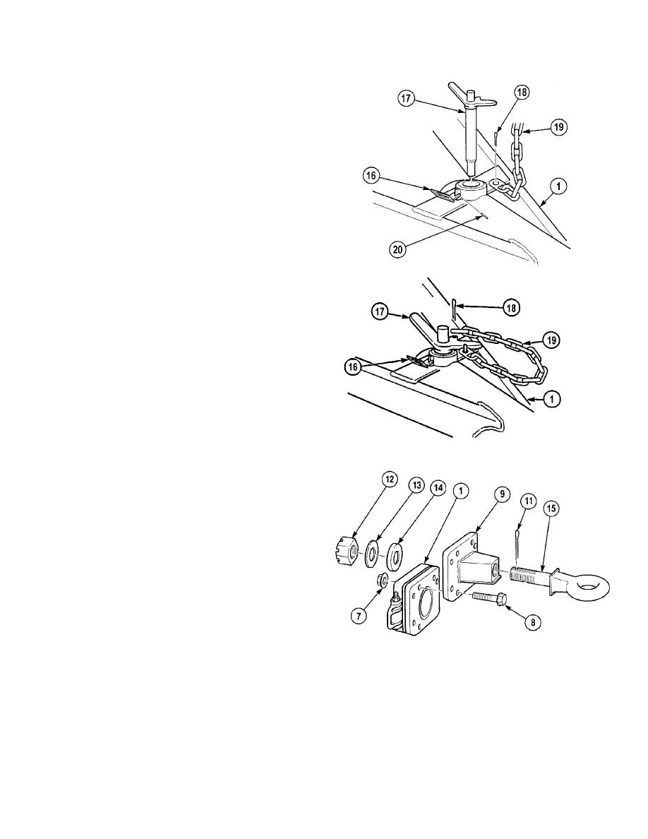
c.
Installation.
NOTE
Perform Step (1) if locking gate was
removed.
(1)
Install locking gate (16) on drawbar (1) with
roll pin (20).
(2)
Install adjusting pin (17) on drawbar (1).
(3)
Install chain (19) on drawbar (1) with cotter
pin (18).
(4)
Install chain (19) on adjusting pin (17) with
cotter pin (18).
(5)
Close locking gate (16) on adjusting pin (17).
NOTE
Step (6) temporarily installs tow ring
bracket on drawbar to aid in torquing of
castle nut. Use bottom two holes of tow
ring bracket and upper two holes of
drawbar.
(6)
Install tow ring bracket (9) on drawbar (1)
with two screws (8) and locknuts (7).
NOTE
If torque requirements can not be
achieved, tow ring bracket should be
replaced.
(7)
Position drawbar tow ring shaft (15) in tow
ring bracket (9).
(8)
Install spacer (14), washer (13) and castle
nut (12) on drawbar tow ring shaft (15).
Tighten castle nut to 2000 lb-ft (2712 N.m)
minimum.
NOTE
If grooves in castle nut do not align
with hole in drawbar tow ring shaft,
perform Step (9).
(9)
Tighten castle nut (12) to next slot in nut.
(10)
Install cotter pin (11) through castle nut (12)
and drawbar tow ring shaft (15). Spread
sides of cotter pin (11) against castle nut (12).
(11)
Remove two locknuts (7), screws (8) and
tow ring bracket (9) from drawbar (1).
Discard locknuts.
4-529
|
|
Privacy Statement - Press Release - Copyright Information. - Contact Us |
