 |
|||
|
|
|||
|
Page Title:
LOCATION AND DESCRIPTION OF MAJOR COMPONENTS. |
|
||
| ||||||||||
|
|
 TM 9-3990-206-14&P
(2)
Two removable, enclosed stowage boxes.
(3)
Folding front and rear walls.
(4)
Capable of accepting a sideboard kit to carry cargo.
(5)
Tiedown rings, 25,000 lb (11,350 kg) and 10,000 lb (4,540 kg) capacity, to secure payloads.
(6)
Forklift pockets to allow movement of the flatrack in loaded/unloaded situations.
(7)
ISO corner castings at the top and bottom of the front and rear walls.
(8)
Removable rollers at the rear of the flatrack.
(9)
Sideboard kit and cargo tarp.
(10)
Twist locks at the front and rear of the flatrack for stacking.
(11)
Pin assemblies at front and rear of the flatrack to allow lowering of front and rear walls.
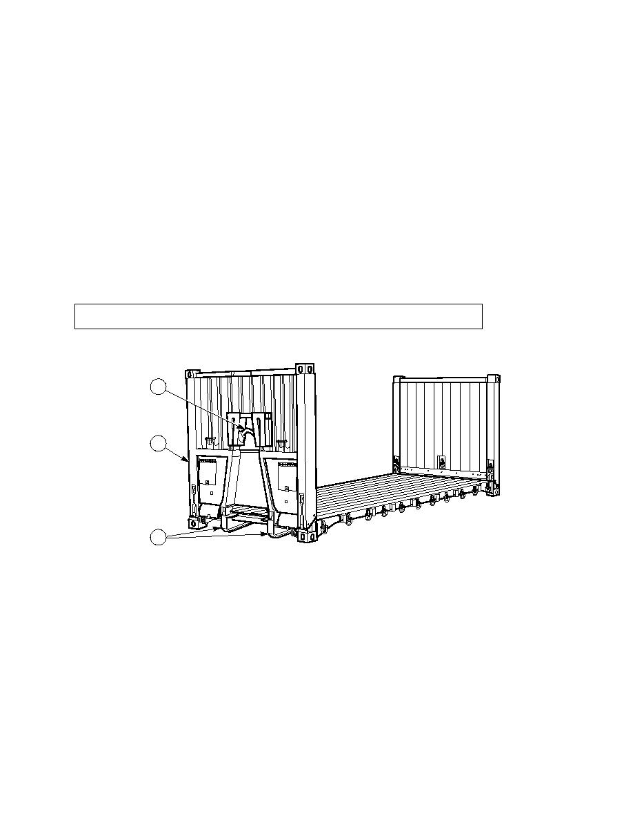
1
2
3
a. Front Wall and Hook Bar. The hook bar (1) on the front wall (2) of the flatrack is used as a lifting point for
the flatrack. The hook bar (1) couples with the LHS hook arm to lift and pull the flatrack onto the truck. The entire
front wall can be lowered onto the flatrack deck to prepare the flatrack for unloaded stacking.
b. Rails. The flatrack rails (3) have locking plates that mate with locks on the truck and trailer to secure the
flatrack for road operations.
|
|
Privacy Statement - Press Release - Copyright Information. - Contact Us |
