|
| |
TM 9-2320-364-10
2-14
2-3. LOCATION AND USE OF CONTROLS AND INDICATORS
(CONT).
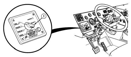
Figure 2-5. CTIS Controller Controls and Indicators
Key
Control or Indicator
Function
1
Rotary Selection Switch
(CTIS)
Do not change CTIS settings when cornering
or wheels are slipping. Damage to drive line may
result.
CTIS ON/OFF switch should be in ON
position at all times. Overspeed protection
will not operate if switch is in OFF position
and tire pressure may not match driving speeds,
resulting in unsafe driving conditions or tire
damage.
NOTE
The rotatory selection switch will still operate
the drive line functions even if the CTIS ON/OFF
switch is set to OFF.
If it becomes necessary to disable the CTIS,
the tires will have to be manually inflated or
deflated.
|