Order this information in Print

Order this information on CD-ROM

Download in PDF Format


Click here to make tpub.com your Home Page

Page Title: Figure 2-5. CTIS Controller Controls and Indicators CONT.
Back | Up | Next

Click here for a printable version

Google


Web
www.tpub.com

Home


Information Categories
.... Administration
Advancement
Aerographer
Automotive
Aviation
Combat
Construction
Diving
Draftsman
Engineering
Electronics
Food and Cooking
Math
Medical
Music
Nuclear Fundamentals
Photography
Religion
USMC
   
Products
  Educational CD-ROM's
Printed Manuals
Downloadable Books


TM 9-2320-364-10 2-16      2-3.  LOCATION AND USE OF CONTROLS AND INDICATORS (CONT). 
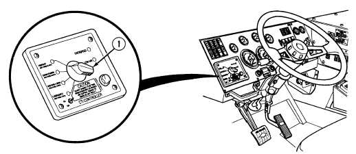
Figure 2-5.  CTIS Controller Controls and Indicators – CONT. Key Control or Indicator Function NOTE 1 Rotary Selection Switch (CTIS) - (Continued)     The rotatory selection switch will still operate the drive line functions even if the CTIS ON/OFF switch is set to OFF.     If  it  becomes  necessary  to  disable  the CTIS,  the  tires  will  have  to  be  manually inflated or deflated. A green LED at each of the four positions will stay lit continuously if the CTIS and driveline lockup are in proper operating mode.  Slow flashing indicates acceptable change.  Rapid flashing   indicates   unacceptable   operating parameters and requires corrective action by the operator.

Privacy Statement - Press Release - Copyright Information. - Contact Us - Support Integrated Publishing

Integrated Publishing, Inc. - A (SDVOSB) Service Disabled Veteran Owned Small Business