|
| |
TM 9-2320-364-10
2-19
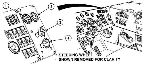
Figure 2-6. Air Panel Controls and Indicators
Key
Control or Indicator
Function
1
Air Pressure Gage
Shows the air pressure (in psi and kPa) in both
sections of the air brake system. Green needle
shows the front brake air reservoir pressure.
Red needle shows the rear brake air reservoir
pressure.
2
Air Filter Restriction
Indicator
Shows the condition of the air filter. Vacuum
in H20 window shows degree of restriction.
Indicator should read less than 20 in. (5.0 kPa)
for normal operation. If indicator latches at 20
in. (5.0 kPa) during operation, truck may
continue to operate until mission is completed.
Air filter must be replaced prior to next
mission. Push the button to reset.
3
PARKING BRAKE
Control
Push to release the truck brakes, pull to apply
the truck brakes. Automatically applies the
parking brakes if air pressure goes below 35
psi (241 kPa).
4
TRAILER AIR SUPPLY
Control
Push to supply air to the trailer air system.
Pull to shut off the trailer air.
|