|
| |
TM 9-2320-364-20-2
2-1805
(1) Start engine and build pressure
to 125 4 psi (861 28 kPa)
(TM 9-2320-364-10).
(2) Turn OFF ENGINE switch.
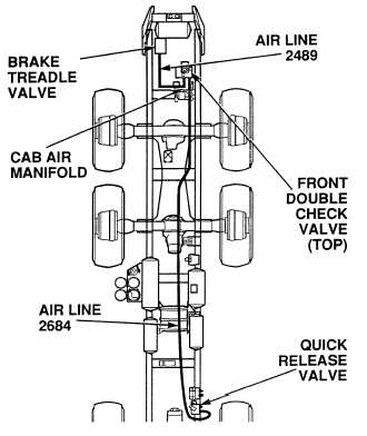
(3) Check air lines 2489 and 2684 for
crimps (see schematic Fig 2-45).
(a) If there are crimps in air lines,
replace air lines (Para 12-36).
(b) If there are no crimps in air lines,
perform Steps (4) and (5) below.
(4) Have assistant apply service brakes.
(5) Check fittings and air lines 2489 and
2684 for leaks (see schematic
Fig 2-45).
(a) If fittings or air lines are leaking,
perform Step (9) below and
tighten/replace fittings and/or
replace air lines (Para 12-36).
(b) If there are no leaks, air lines
and fittings are OK. Perform
Step (6) below.
(6) Check brake treadle valve for leaks
(see schematic Fig 2-45 and 2-46).
(a) If brake treadle valve leaks,
perform Step (9) below and
replace valve (Para 12-4).
(b) If there are no leaks, perform
Step (7) below.
(7) Check front double check valve (top)
for leaks (see schematic Fig 2-45).
(a) If front double check valve (top)
leaks, perform Step (9) below and
replace valve (Para 12-11).
(b) If there are no leaks, perform
Step (8) below.
(8) Check quick release valve for leaks
(see schematic Fig 2-45 and 2-46).
(a) If quick release valve leaks,
perform Step (9) below and
replace valve (Para 12-39).
(b) If there are no leaks, perform
Step (9) below.
(9) Release service brakes.
VISUAL/AUDIBLE INSPECTION
Wear safety goggles when performing leakage tests on valves. Failure to do so may result in serious
eye injury due to high pressure air.
If air lines are under high pressure when they are disconnected, they can whip around and cause injury
to personnel. Caution should be exercised when loosening or disconnecting air line fittings.
|