|
| |
TM 9-2320-364-20-2
2-879
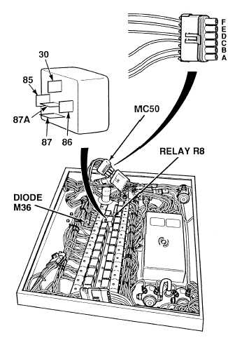
Table 2-29. ECB/ATEC Wire Harness
Connector MC50.
(1) Suspect wire(s) in electrical control
box wire harness could be faulty from
connector MC50 to terminal 85 of the
following relay(s): RETARDER relay
R8, C.K. TRANS relay R9, REVERSE
relay R10, NEUTRAL START
relay R11.
(2) Is there continuity on wire 211
between connector MC50, terminal B
and relay R8, terminal 30?
(a) If there is no continuity, repair
wire (see schematic Fig 2-21) or
notify DS Maintenance.
(b) If there is continuity, wire is OK.
(c) If all wires are OK, perform
Steps (4) and (5) below and
replace shift selector (Para 8-2).
Go to Step 6 of this Fault.
(3) Repeat Step (2) for relays and
terminals listed in Table 2-29.
(4) Connect connector MC50.
(5) Install two ECB covers and 15 screws.
Remove all jewelry such as rings, dog tags, bracelets, etc. If jewelry or tools contact positive electrical
circuits, a direct short may result. Damage to equipment, injury or death to personnel may occur.
Circuit breakers CB5, CB6, CB12, CB20, CB22, CB23 and relays R3, R13 - R19, R26, R28, R32, R33
are always electrically hot and can cause severe injury to personnel. Care must be exercised when working
under the electrical circuit board cover.
NOTE
Electrical control box connector MC50,
terminal F interfaces with dash lighting
circuits in cab through wire 1052. Go to
“Electrical Troubleshooting” (Para 2-20)
if problem with lighting controls or
illumination at shift selector.
Relay
Relay
terminal
MC50
terminal
Wire
R8
R9
R10
R11
30
85
85
85
B
C
D
Diode M36
211
215
214
231
CONTINUITY TEST
|