|
| |
TM 9-2320-364-20-2
2-1861
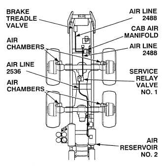
(1) Check air lines 2488 and 2536 for
crimps (see schematic Fig 2-44).
(a) If there are crimps in air lines,
replace air lines (Para 12-36).
(b) If there are no crimps in air lines,
perform Steps (2) and (3) below.
(2) Apply service brakes
(TM 9-2320-364-10).
(3) Check fittings and air lines 2488, 2536
for leaks (see schematic Fig 2-44).
(a) If fittings or air lines are leaking,
perform Step (6) below and
tighten/replace fittings and/or
replace air lines (Para 12-36).
(b) If there are no leaks, fittings and
air lines are OK. Perform
Step (4) below.
(4) Check service relay valve No. 1 for
leaks.
(a) If service relay valve No. 1
leaks, perform Step (6) below
and replace valve (Para 12-13).
(b) If there are no leaks, perform
Step (5) below.
(5) Check air chambers for leaks.
(a) If air chamber leaks, perform
Step (6) below and replace air
chamber (Para 12-9).
(b) If there are no leaks, perform
Step (6) below.
(6) Release service brakes.
VISUAL/AUDIBLE INSPECTION
Wear safety goggles when performing leakage tests on valves. Failure to do so may result in serious eye
injury due to high pressure air.
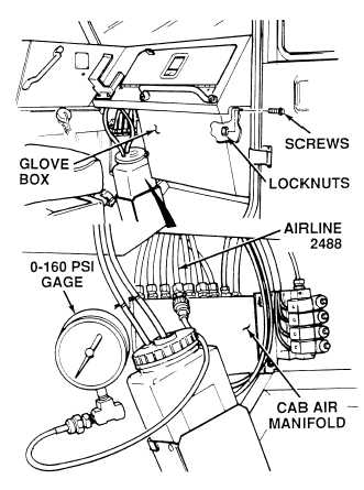
(1) Remove six screws, locknuts and
glove box. Discard locknuts.
(2) Disconnect air line 2488 from cab
air manifold.
(3) Connect 0 to 160 psi (0-1103 kPa)
gage to air line 2488.
(4) Apply service brakes
(TM 9-2320-364-10).
(a) If there are not 125 4 psi
(861 28 kPa) present at air line
2488, perform Steps (5)
through (7) below and replace
brake treadle valve (Para 12-4).
(b) If there are 125 4 psi
(861 28 kPa) present at air line
2488, brake treadle valve is OK.
(5) Release service brakes.
(6) Remove gage and connect air line
2488 to cab air manifold.
(7) Install glove box, six screws and
locknuts.
BRAKE TREADLE VALVE TEST
|