|
| |
TM 9-2320-364-20-2
2-901
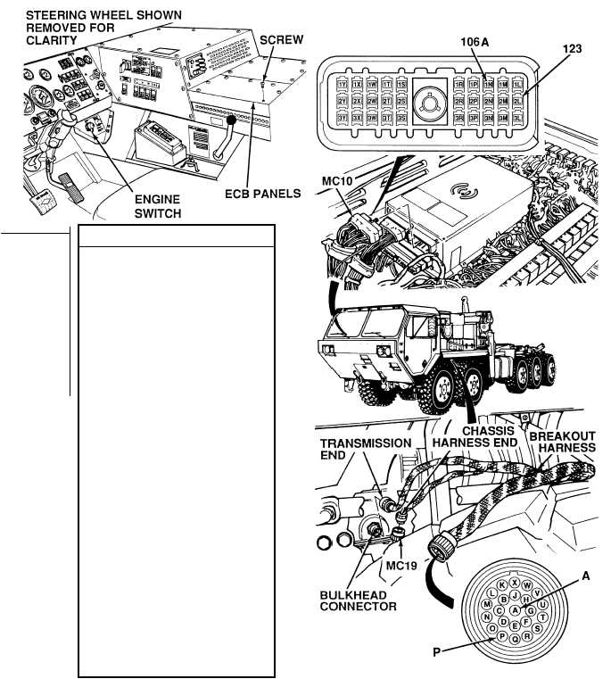
(1) Remove 15 screws and two
ECB covers.
(2) Loosen screw and disconnect
connector MC10 from ATEC ECU.
(3) Connect transmission connector
MC19 to breakout harness
chassis end connector.
(4) Is there continuity on wire 123
between breakout harness, terminal
A and harness connector MC10,
terminal 2L?
(a) If there is no continuity, repair
wire 123 (see schematic
Fig 2-22) or notify DS
Maintenance.
(b) If there is continuity, wire 123
is OK.
(5) Is there continuity on wire 106A/B
between breakout harness,
terminal P and harness connector
MC10, terminal 1N?
(a) If there is no continuity, repair
wire 106A/B (see schematic
Fig 2-22) or notify DS
Maintenance.
(b) If there is continuity,
wire 106A/B is OK.
(6) Connect connector MC10 to ATEC
ECU and tighten screw.
(7) Install two ECB covers and 15
screws.
(8) Disconnect breakout harness
transmission and chassis end
connectors from transmission
bulkhead and MC19 connector.
(9) Connect transmission connector
MC19 to transmission bulkhead
connector.
(10) Install left rear skirt on underside of
fender (Para 17-34).
CONTINUITY TEST
Remove all jewelry such as rings, dog tags, bracelets, etc. If jewelry or tools contact positive electrical
circuits, a direct short may result. Damage to equipment, injury or death to personnel may occur.
Voltage is always present at circuit breakers CB5, CB6, CB12, CB20, CB22, CB23 and relays R3, R13 - R19,
R26, R28, R32, R33 and can cause severe injury to personnel. Non-metallic tools shall be used when removing
|