|
| |
TM 9-2320-364-20-2
2-943
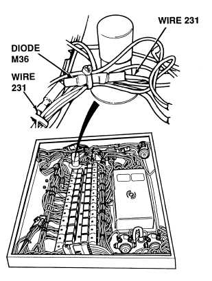
(1) Tag, mark and disconnect wires 231
from both sides of diode M36.
(2) Set multimeter select switch to
diode check position.
(3) Connect positive (+) lead to female
end of diode.
(4) Connect negative (–) lead to male end
of diode.
(a) If a vdc is not present, diode is
faulty, replace diode.
(b) If a vdc value is present, go to
Step (5).
(5) Connect positive (+) lead to male end
of diode.
(6) Connect negative (–) lead to female
end of diode.
(a) If a vdc value is not present,
diode is OK.
(b) If a vdc value is present, diode is
faulty, replace diode.
DIODE TEST
Remove all jewelry such as rings, dog tags, bracelets, etc. If jewelry or tools contact positive electrical
circuits, a direct short may result. Damage to equipment, injury or death to personnel may occur.
Circuit breakers CB5, CB6, CB12, CB20, CB22, CB23 and relays R3, R13 - R19, R26, R28, R32, R33
are always electrically hot and can cause severe injury to personnel. Care must be exercised when
working under the electrical circuit board cover.
|