|
| |
TM 9-2320-364-20-2
2-947
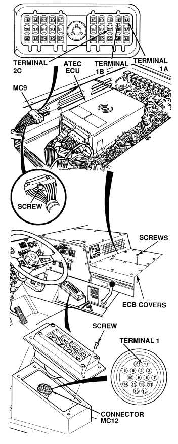
(1) Loosen screw and disconnect
connector MC9 from ATEC ECU.
(2) Is there continuity on wire 210A
between shift selector connector
MC12, terminal 1 and ATEC ECU
connector MC9, terminal 2C?
(a) If there is no continuity, perform
Steps (3) and (4) below and repair
wire 210A (see schematic
Fig 2-25) or notify DS
Maintenance.
(b) If there is continuity, wire 210A
is OK.
(3) Connect shift selector connector
MC12 to shift selector.
(4) Install shift selector and four screws.
CONTINUITY TEST
Remove all jewelry such as rings, dog tags,
bracelets, etc. If jewelry or tools contact
positive electrical circuits, a direct short
may result. Damage to equipment, injury or
death to personnel may occur.
Circuit breakers CB5, CB6, CB12, CB20,
CB22, CB23 and relays R3, R13 - R19, R26,
R28, R32, R33 are always electrically hot
and can cause severe injury to personnel.
Care must be exercised when working
under the electrical circuit board cover.
(1) Is there continuity on wire 208
between ATEC ECU connector MC9,
terminal 1A and a known good
ground?
(a) If there is no continuity, perform
Steps (3) and (4) below, and
repair wire 208 (see schematic
Fig 2-25) or notify DS
Maintenance.
(b) If there is continuity, wire 208
is OK.
(2) Is there continuity on wire 209
between ATEC ECU connector MC9,
terminal 1B and a known good
ground?
(a) If there is no continuity, perform
Steps (3) and (4) below, and
repair wire 208 (see schematic
Fig 2-25) or notify DS
Maintenance.
(b) If there is continuity, wire 209
is OK.
(3) Connect connector MC9 to ATEC
ECU and tighten screw.
(4) Install two ECB covers and 15 screws.
CONTINUITY TEST
|