|
| |
TM 9-2320-364-20-2
2-973
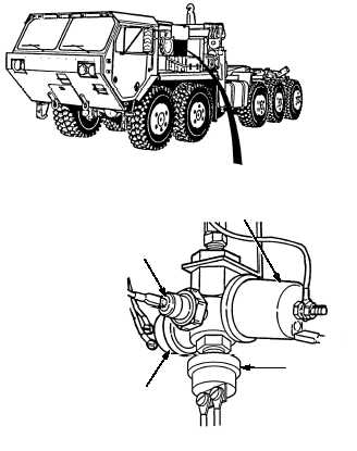
(1) Check oil sending units for leakage or
damage.
(a) If oil sending units are loose,
leaking, or damaged, tighten or
replace damaged units
(Para 7-79).
(b) If oil sending units are not leaking,
oil sending units are OK.
(2) Install left side noise panel, eight
screws, washers, and lockwashers.
(3) Install right side noise panel
(Para 17-26).
VISUAL INSPECTION
(1) Start engine (TM 9-2320-364-10).
(2) Scroll down to mode 17 OIL
PRESSURE PSI.
(3) Increase engine speed to 1800 to
2100 RPM.
(a) If engine oil pressure is less than
35 psi (241 kPa), perform Steps
(3) through (5) below and notify
DS Maintenance.
(b) If engine oil pressure is between
35 and 40 psi (241 and 276 kPa),
fault has been corrected.
(3) Clear codes (Para 2-11).
(4) Turn OFF ENGINE switch.
(5) Disconnect DDR from DDL
connector MC13.
VERIFY REPAIR
ENGINE OIL
PRESSURE
SENDING UNIT
HOUR METER
SENSOR
ATEC, OIL
PRESSURE
SENSOR
ALT, OIL
PRESSURE
SENSOR (IF
EQUIPPED)
|