|
| |
TM 9-2320-364-20-2
2-1055
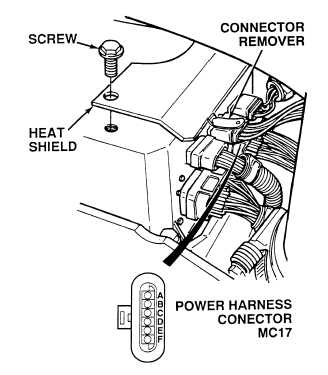
(1) Remove two screws and heat shield
from DDEC ECM.
(2) Disconnect power harness connector
MC17 from DDEC ECM with
connector remover.
(3) Connect positive (+) multimeter lead
to wires 241 at DDEC ECM power
connector, terminals A and B one at
a time.
(4) Connect negative (–) multimeter lead
to a known good ground.
(a) If 10 to 14 vdc are not present,
repair wires 241 (see schematic
Fig 2-3) or notify DS Maintenance.
(b) If 10 to 14 vdc are present, go to
Step (5) below.
(5) Connect positive (+) multimeter lead
to wires 240, terminals E and F one
at a time.
(a) If 10 to 14 vdc are not present,
repair wires 240 (see schematic
Fig 2-3) or notify DS Maintenance.
(b) If 10 to 14 vdc are present, wires
240 are OK. Go to Step (6)
below.
(6) Connect power harness connector
MC17 to DDEC ECM.
(7) Install heat shield and two
mounting screws.
VOLTAGE TEST
Remove all jewelry such as rings, dog tags, bracelets, etc. If jewelry or tools contact positive electrical
circuits, a direct short may result. Damage to equipment, injury or death to personnel may occur.
Circuit breakers CB5, CB6, CB12, CB20, CB22, CB23 and relays R3, R13 - R19, R26, R28, R32, R33
are always electrically hot and can cause severe injury to personnel. Care must be exercised when
working under the electrical circuit board cover.
|