|
| |
TM 9-2320-364-20-2
2-1187
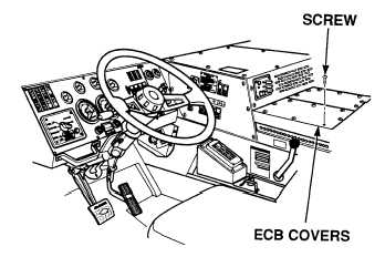
(1) Remove 15 screws and two ECB
covers.
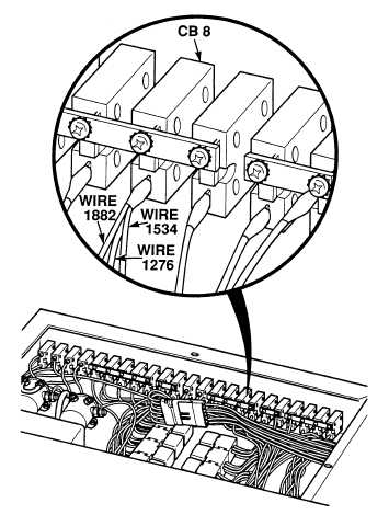
(2) Connect positive (+) multimeter lead
to wire 1276 at dash lock up circuit
breaker CB8.
(3) Connect negative (–) multimeter lead
to a known good ground.
(4) Turn ON ENGINE switch
(TM 9-2320-364-10).
(a) If 10 to 14 vdc are not present,
turn OFF ENGINE switch and
replace dash lock up circuit
breaker (Para 7-16).
(b) If 10 to 14 vdc are present, turn
OFF ENGINE switch and repair
wire 1276 (see schematic
Fig 2-28) or notify DS
Maintenance.
(5) Install two ECB covers and 15 screws.
VISUAL INSPECTION
Remove all jewelry such as rings, dog tags, bracelets, etc. If jewelry or tools contact positive electrical
circuits, a direct short may result. Damage to equipment, injury or death to personnel may occur.
Circuit breakers CB5, CB6, CB12, CB20, CB22, CB23 and relays R3, R13 - R19, R26, R28, R32, R33
are always electrically hot and can cause severe injury to personnel. Care must be exercised when
working under the electrical circuit board cover.
(1) Start engine (TM 9-2320-364-10).
(2) Inspect gage reading.
(a) If gage gives incorrect reading,
fault not corrected. Turn OFF
ENGINE switch and Notify DS
Maintenance.
(b) If gage gives correct reading, fault
has been corrected.
(3) Turn OFF ENGINE switch.
VERIFY REPAIR
|