|
| |
TM 9-2320-364-20-2
2-1207
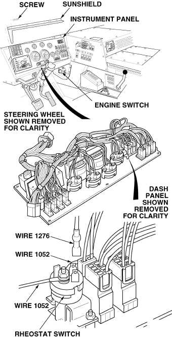
(1) Connect positive (+) multimeter lead
to wire 1052 at thumbwheel rheostat
switch.
(2) Connect negative (–) multimeter lead
to a known good ground.
(3) Turn ON ENGINE switch
(TM 9-2320-364-10).
(4) Turn thumbwheel rheostat switch to
full brightness.
(a) If 10 to 14 vdc are not present,
perform Steps (5) and (6) below
and replace thumbwheel rheostat
switch (Para 7-26).
(b) If 10 to 14 vdc are present,
thumbwheel rheostat switch is
OK.
(5) Turn OFF ENGINE switch.
(6) Install instrument panel and sunshield
with ten screws.
VOLTAGE TEST
Remove all jewelry such as rings, dog tags, bracelets, etc. If jewelry or tools contact positive electrical
circuits, a direct short may result. Damage to equipment, injury or death to personnel may occur.
(1) Turn ON ENGINE switch
(TM 9-2320-364-10).
(2) Adjust rheostat to full bright.
(3) Observe instrument lights.
(a) If instrument lights do not operate,
fault not corrected. Turn OFF
ENGINE switch and notify DS
Maintenance.
(b) If instrument lights operate, fault
has been corrected.
(4) Turn OFF ENGINE switch.
VERIFY REPAIR
|