|
| |
TM 9-2320-364-20-2
2-1295
(1) Set multimeter select switch to volts
dc.
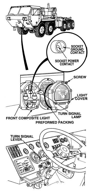
(2) Connect positive (+) multimeter lead
to socket power contact of turn signal
light socket.
(3) Connect negative (–) multimeter lead
to a known good ground.
(4) Turn on left turn signal
(TM 9-2320-364-10).
(a) If 2 to 10 vdc are not present,
turn off left turn signal and go to
Step 4 of this Fault.
(b) If 2 to 10 vdc are present, turn off
left turn signal and go to Step 3 of
this Fault.
VOLTAGE TEST
Remove all jewelry such as rings, dog tags, bracelets, etc. If jewelry or tools contact positive electrical
circuits, a direct short may result. Damage to equipment, injury or death to personnel may occur.
(1) Set multimeter select switch to ohms.
(2) Is there continuity between turn signal
socket ground contact and a known
good ground?
(a) If there is no continuity, replace
left front composite light
(Para 7-46).
(b) If there is continuity, perform
Steps (3) and (4) below and notify
DS Maintenance.
(3) Install turn signal lamp.
(4) Install preformed packing, composite
light cover and tighten five screws.
CONTINUITY TEST
NOTE
Voltage will pulsate between 2 to 10 vdc
during turn signal voltage test.
|