|
| |
TM 9-2320-364-20-2
2-1367
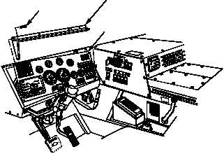
INSTRUMENT PANEL
SCREW
SUNSHIELD
STEERING WHEEL
SHOWN REMOVED
FOR CLARITY
INSTRUMENT
PANEL
SHOWN
REMOVED
FOR CLARITY
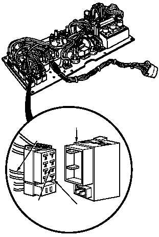
SWITCH
CONNECTOR
BLACKOUT
DRIVE SWITCH
WIRE 1679
WIRE 1674
1
5
(1) Remove ten screws and sunshield
from instrument panel.
(2) Pull top of instrument panel towards
steering wheel.
(3) Disconnect BLACKOUT DRIVE
switch connector from BLACKOUT
DRIVE switch.
(4) Connect positive (+) multimeter lead
to wire 1674 at BLACKOUT DRIVE
switch, terminal 5.
(5) Connect negative (–) multimeter
lead to a known good ground.
(6) Turn ON ENGINE switch
(TM 9-2320-364-10).
(a) If 10 to 14 vdc are not present,
turn OFF ENGINE switch and
repair wire 1674 (see schematic
Fig 2-35) or notify DS
Maintenance.
(b) If 10 to 14 vdc are present,
wire 1674 is OK.
(7) Turn OFF ENGINE switch.
VOLTAGE TEST
Remove all jewelry such as rings, dog tags, bracelets, etc. If jewelry or tools contact positive electrical
circuits, a direct short may result. Damage to equipment, injury or death to personnel may occur.
(1) Set multimeter select switch to
ohms.
(2) Is continuity measured between
BLACKOUT DRIVE switch,
terminals 5 and 1?
(a) If there is no continuity,
replace BLACKOUT DRIVE
switch (Para 7-27).
(b) If there is continuity, repair
wire 1679 (see schematic
Fig 2-35) or notify DS
Maintenance.
(3) Connect BLACKOUT DRIVE switch
connector to BLACKOUT DRIVE
switch.
(4) Install instrument panel and
sunshield with ten screws.
(5) Install lamp and reflector.
(6) Install face plate and tighten
four screws.
(7) Connect wire 1679 to blackout drive
light lead wire 19.
CONTINUITY TEST
|