|
| |
TM 9-2320-364-20-2
2-1375
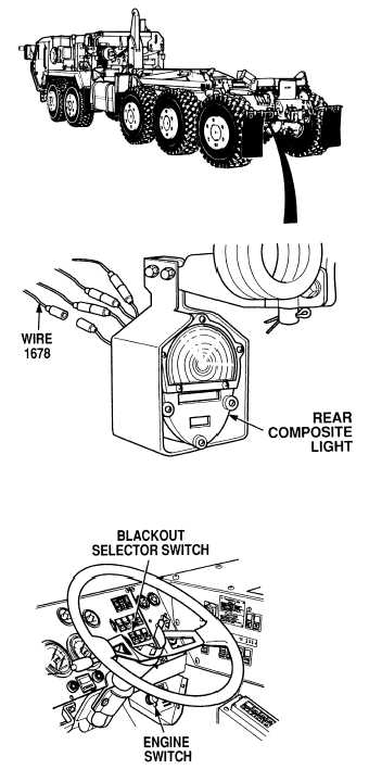
(1) Pull wire out back of bracket area to
expose four connectors.
(2) Disconnect wire 1678.
(3) Connect positive (+) multimeter lead
to wire 1678.
(4) Connect negative (–) multimeter lead
to a known good ground.
(5) Turn ON ENGINE switch
(TM 9-2320-364-10).
(6) While assistant fully applies brake
pedal, observe multimeter.
(a) If 10 to 14 vdc are not present,
perform Steps (7) through (9)
below and repair wire 1678 (see
schematic Fig 2-35).
(b) If 10 to 14 vdc are present,
perform Steps (7) through (9)
below and replace rear composite
light (Para 7-47).
(7) Release brake pedal.
(8) Turn off BLACKOUT LIGHTS
selector switch.
(9) Turn OFF ENGINE switch.
VOLTAGE TEST
Remove all jewelry such as rings, dog tags, bracelets, etc. If jewelry or tools contact positive electrical
circuits, a direct short may result. Damage to equipment, injury or death to personnel may occur.
|