|
| |
TM 9-2320-364-20-2
2-1393
(1) Turn ON ENGINE switch
(TM 9-2320-364-10).
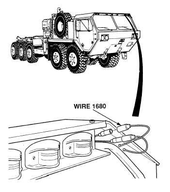
(2) Observe blackout clearance lights.
(a) If both clearance lights do not
operate, turn OFF ENGINE
switch and repair wire 1680
between marker light splice and
clearance light splice
(see schematic Fig 2-35)
or notify DS Maintenance.
(b) If one clearance light does
operate, turn OFF ENGINE
switch and go to Step 3 of
this Fault.
VISUAL INSPECTION
Remove all jewelry such as rings, dog tags,
bracelets, etc. If jewelry or tools contact
positive electrical circuits, a direct short
may result. Damage to equipment, injury or
death to personnel may occur.
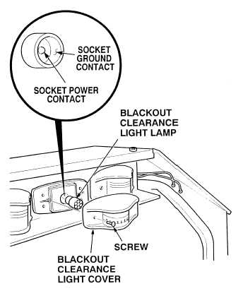
(1) Remove two screws, blackout
clearance light cover and blackout
clearance light lamp from blackout
clearance light.
(2) Set multimeter select switch to
volts dc.
(3) Connect positive (+) multimeter lead
to socket power contact of clearance
light lamp socket.
(4) Connect negative (–) multimeter lead
to a known good ground.
(5) Turn ON ENGINE switch
(TM 9-2320-364-10).
(a) If 10 to 14 vdc are not present,
turn OFF ENGINE switch and go
to Step 5 of this Fault.
(b) If 10 to 14 vdc are present,
turn OFF ENGINE switch and go
to Step 4 of this Fault.
VOLTAGE TEST
|