|
| |
TM 9-2320-364-20-2
2-1469
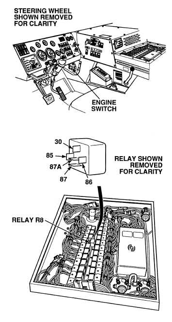
(1) Connect positive (+) multimeter lead
to wire 1839 at retarder relay R8,
terminal 30.
(2) Connect negative (–) multimeter lead
to a known good ground.
(3) Start engine (TM 9-2320-364-10).
(4) While assistant applies throttle control
for ten seconds at 2000 rpm and
quickly releases throttle control,
observe multimeter.
(a) If 10 to 14 vdc are not present
while engine decelerates, turn
OFF ENGINE switch and repair
wire 1839 (see schematic
Fig 2-38) or notify DS
Maintenance.
(b) If 10 to 14 vdc are present
while engine decelerates, wire
1839 is OK.
(5) Turn OFF ENGINE switch.
VOLTAGE TEST
Remove all jewelry such as rings, dog tags, bracelets, etc. If jewelry or tools contact positive electrical
circuits, a direct short may result. Damage to equipment, injury or death to personnel may occur.
Circuit breakers CB5, CB6, CB12, CB20, CB22, CB23 and relays R3, R13 - R19, R26, R28, R32, R33
are always electrically hot and can cause severe injury to personnel. Care must be exercised when
working under the electrical circuit board cover.
Relay test must be performed with relay
partially removed.
NOTE
|