|
| |
TM 9-2320-364-20-2
2-1487
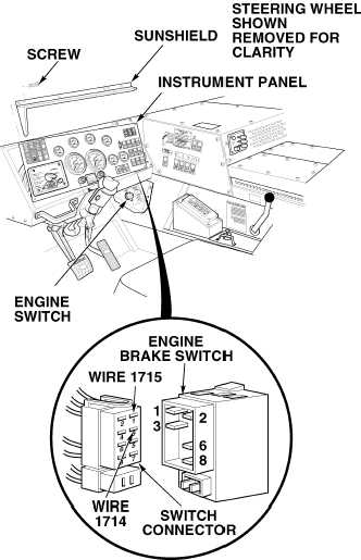
(1) Remove ten screws and sunshield
from instrument panel.
(2) Pull top of instrument panel towards
steering wheel.
(3) Remove engine brake switch.
(4) Set multimeter select switch to
volts dc.
(5) Connect positive (+) multimeter to
wire 1714 at engine brake switch
connector, terminal 3.
(6) Connect negative (–) multimeter
lead to a known good ground.
(7) Start engine (TM 9-2320-364-10).
(8) Shift tranfer case to N (Neutral).
(9) Shift transmission to D (Drive).
(10) While assistant applies throttle
control for ten seconds at 2000 rpm
and quickly releases throttle control,
observe multimeter.
(a) If 10 to 14 vdc are not present,
turn OFF ENGINE switch and
repair wire 1714 (see schematic
Fig 2-38) or notify DS
Maintenance.
(b) If 10 to 14 vdc are present,
wire 1714 is OK.
(11) Turn OFF ENGINE switch.
(12) Close top engine access cover.
(13) Install right side noise panel (Para
17-26).
VOLTAGE TEST
Remove all jewelry such as rings, dog tags, bracelets, etc. If jewelry or tools contact positive electrical
circuits, a direct short may result. Damage to equipment, injury or death to personnel may occur.
(1) Set multimeter select switch to ohms.
(2) Set engine brake switch to high
position.
(3) Is there continuity between terminals
3 and 1 at engine brake switch?
(a) If there is no continuity, replace
engine brake switch (Para 7-27).
(b) If there is continuity, repair
wire 1715 (see schematic
Fig 2-38) or notify DS
Maintenance.
(4) Install engine brake switch.
(5) Install instrument panel and
sunshield with ten screws.
CONTINUITY TEST
|