|
| |
TM 9-2320-364-20-2
2-1497
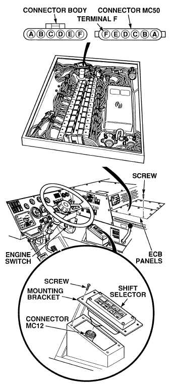
(1) Remove 15 screws and two ECB
covers.
(2) Disconnect connector MC50.
(3) Set multimeter select switch to
volts dc.
(4) Connect positive (+) multimeter lead
to wire 1052 at harness connector
MC50, terminal F.
(5) Connect negative (–) multimeter lead
to a known good ground.
(6) Turn ON ENGINE switch
(TM 9-2320-364-10).
(a) If 10 to 14 vdc are not present,
turn OFF ENGINE switch and
repair wire 1052 (see schematic
Fig 2-20) or notify DS
Maintenance.
(b) If 10 to 14 vdc are present,
turn OFF ENGINE switch and
repair wire 233 (see schematic
Fig 2-20) or notify DS
Maintenance.
(7) Connect connector MC50.
(8) Install two ECB covers and 15 screws.
(9) Connect connector MC12 and install
shift selector and four screws.
VOLTAGE TEST
Remove all jewelry such as rings, dog tags, bracelets, etc. If jewelry or tools contact positive electrical
circuits, a direct short may result. Damage to equipment, injury or death to personnel may occur.
Circuit breakers CB5, CB6, CB12, CB20, CB22, CB23 and relays R3, R13 - R19, R26, R28, R32, R33
are always electrically hot and can cause severe injury to personnel. Care must be exercised when
working under the electrical circuit board cover.
|