|
| |
TM 9-2320-364-20-2
2-1539
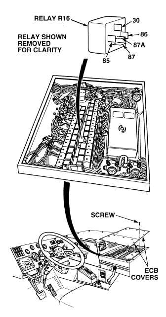
(1) Remove 15 screws and two
ECB covers.
(2) Connect positive (+) multimeter lead
to wire 1676 at trailer R.H. turn relay
R16, terminal 30.
(3) Connect negative (–) multimeter lead
to known good ground.
(4) Observe multimeter.
(a) If 22 to 28 vdc are not present,
repair wire 1676 (see schematic
Fig 2-32) or notify DS
Maintenance.
(b) If 22 to 28 vdc are present, wire
1676 is OK.
VOLTAGE TEST
Remove all jewelry such as rings, dog tags, bracelets, etc. If jewelry or tools contact positive electrical
circuits, a direct short may result. Damage to equipment, injury or death to personnel may occur.
Circuit breakers CB5, CB6, CB12, CB20, CB22, CB23 and relays R3, R13 - R19, R26, R28, R32, R33
are always electrically hot and can cause severe injury to personnel. Care must be exercised when
working under the electrical circuit board cover.
(1) Connect positive (+) multimeter lead
to wire 1004 at trailer R.H. turn relay
R16, terminal 86.
(2) Connect negative (–) multimeter lead
to known good ground.
(3) While assistant applies brake pedal,
observe multimeter.
(a) If 10 to 14 vdc are not present,
release brake pedal and repair
wire 1004 (see schematic
Fig 2-32) or notify DS
Maintenance.
(b) If 10 to 14 vdc are present, wire
1004 is OK between relay R16,
terminal 86 and splice before
connector MC7.
(4) Release brake pedal.
VOLTAGE TEST
Relay test must be performed with relay
partially removed.
NOTE
Relay test must be performed with relay
partially removed.
NOTE
|