|
| |
TM 9-2320-364-20-2
2-1565
(1) Set multimeter select switch to ohms.
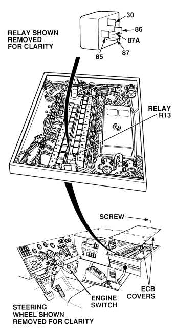
(2) Is there continuity between trailer
blackout stoplight relay R13, terminal
85 and a known good ground?
(a) If there is no continuity, repair
wire 1435 (see schematic
Fig 2-35) or notify DS
Maintenance.
(b) If there is continuity, wire 1435 is
OK.
CONTINUITY TEST
Remove all jewelry such as rings, dog tags, bracelets, etc. If jewelry or tools contact positive electrical
circuits, a direct short may result. Damage to equipment, injury or death to personnel may occur.
Circuit breakers CB5, CB6, CB12, CB20, CB22, CB23 and relays R3, R13 - R19,R26, R28, R32, R33
are always electrically hot and can cause severe injury to personnel. Care must be exercised when
working under the electrical circuit board cover.
(1) Set multimeter select switch to
volts dc.
(2) Connect positive (+) multimeter
lead to wire 1678C at relay R13,
terminal 87 (Para 2-11).
(3) Connect negative (–) multimeter
lead to known good ground.
(4) Turn on BLACKOUT MARKER
lights switch (TM 9-2320-364-10).
(5) Turn on BLACKOUT LIGHTS
selector switch.
(6) Turn ON ENGINE switch.
(7) While assistant applies brake pedal,
observe multimeter.
(a) If 22 to 28 vdc are not present,
perform Steps (8) through (11)
below and replace relay R13
(Para 7-95).
(b) If 22 to 28 vdc are present,
perform Steps (8) through (11)
below and repair wire 1678C
(see schematic Fig 2-35) or
notify DS Maintenance.
(8) Turn OFF ENGINE switch.
(9) Turn off BLACKOUT LIGHTS
selector switch.
(10)
Turn off BLACKOUT MARKER
lights switch.
(11)
Install two ECB covers
and 15 screws.
VOLTAGE TEST
NOTE
Relay test must be performed with relay
partially removed.
NOTE
Relay test must be performed with relay
partially removed.
|