|
| |
TM 9-2320-364-20-2
2-1593
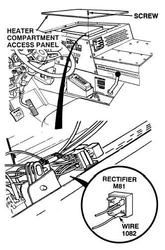
(1) Remove eight screws and heater
compartment access panel.
(2) Set multimeter select switch to
volts dc.
(3) Connect positive (+) multimeter lead
to wire 1082 at AC terminal of rectifier.
(4) Connect negative (–) multimeter lead
to a known good ground.
(5) Turn ON ENGINE switch
(TM 9-2320-364-10).
(a) If 22 to 28 vdc are not present,
perform Step (6) below and
repair wire 1082 (see schematic
Fig 2-42) or notify DS
Maintenance.
(b) If 22 to 28 vdc are present,
wire 1082 is OK.
(6) Turn OFF ENGINE switch.
VOLTAGE TEST
Remove all jewelry such as rings, dog tags, bracelets, etc. If jewelry or tools contact positive electrical
circuits, a direct short may result. Damage to equipment, injury or death to personnel may occur.
(1) Tag, mark and remove wires from
rectifier M81.
(2) Set multimeter select switch to diode
check.
(3) Connect positive (+) multimeter lead
to rectifier negative terminal.
(4) Connect negative (–) multimeter lead
to rectifier AC terminals one at a time.
(a) If any vdc are not present, replace
rectifier (Para 7-19).
(b) If any vdc are present, go to Step
(5) below.
(5) Connect negative (–) multimeter lead
to rectifier positive terminal.
(6) Connect positive (+) multimeter lead
to rectifier AC terminals one at a time.
(a) If any vdc are not present, replace
rectifier (Para 7-19).
(b) If any vdc are present, rectifier is
OK.
(7) Connect wires to rectifier.
RECTIFIER TEST
|