|
| |
TM 9-2320-364-20-2
2-1629
NEG (–)
TERMINAL
DUVAC
COVER
WASHER
LOCK–
WASHER
SCREW
MULTIMETER
TWO
MULTIMETER
ONE
BATTERY
BOX COVER
TERMINAL A
DUVAC
CONTROLLER
POS. (+)
TERMINAL
”A” GROUP
”B” GROUP
HEADLIGHT
SWITCH
FAN
CONTROL
SWITCH
ENGINE
SWITCH
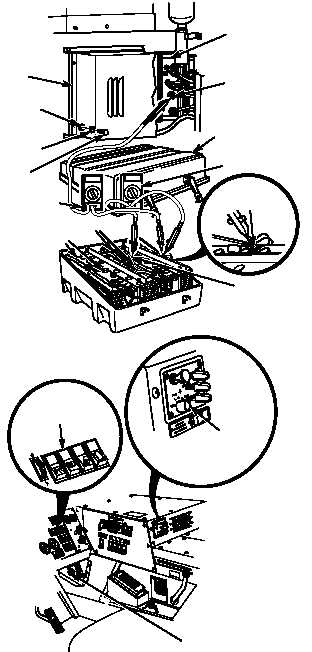
(1) Remove battery box cover
(TM 9-2320-364-10).
(2) Set multimeter select switch to
volts dc.
(3) Connect multimeter one positive (+)
lead to positive (+) terminal and
multimeter one negative (–) lead
to negative (–) terminal on
group ”A” batteries.
(4) Remove four screws, lockwashers,
washers and DUVAC cover.
Discard lockwashers.
(5) Set multimeter select switch to
volts dc.
(6) Connect multimeter two positive (+)
lead to terminal A of DUVAC
controller and multimeter two
negative
(–) lead to negative (–)
terminal of group ”A” batteries.
(7) Start engine and turn on headlights
and heater.
(8) Observe voltage indicated on
multimeter one.
(a) If 13.8 - 14.2 vdc are not
present, adjust voltage
regulator (Para 7-7).
(b) If 13.8 - 14.2 vdc are present,
voltage regulator adjustment is
OK.
(9) Turn off heater, headlights and
engine switch.
(10) Install DUVAC cover with four
screws, lockwashers and washers.
(11) Install battery box cover.
VOLTAGE TEST
Remove all jewelry such as rings, dog tags, bracelets, etc. If jewelry or tools contact positive electrical
circuits, a direct short may result. Damage to equipment, injury or death to personnel may occur.
Terminal 1 and terminal 2 at DUVAC controller are electrically hot all of the time. Ensure DUVAC cover
does not contact either terminal. Damage to equipment, injury or death to personnel may occur.
NOTE
DUVAC controller resets to the 24 vdc charge
mode approximately every 55 seconds. Make
sure multimeter two reads 13-15 vdc indicating
the system is in the 12 vdc charge mode while
reading on multimeter one is taken.
|