Order this information in Print

Order this information on CD-ROM

Download in PDF Format


Click here to make tpub.com your Home Page

Page Title: VERIFY REPAIR
Back | Up | Next

Click here for a printable version

Google


Web
www.tpub.com

Home


Information Categories
.... Administration
Advancement
Aerographer
Automotive
Aviation
Combat
Construction
Diving
Draftsman
Engineering
Electronics
Food and Cooking
Math
Medical
Music
Nuclear Fundamentals
Photography
Religion
USMC
   
Products
  Educational CD-ROM's
Printed Manuals
Downloadable Books


TM 9-2320-364-20-2      2-1641 
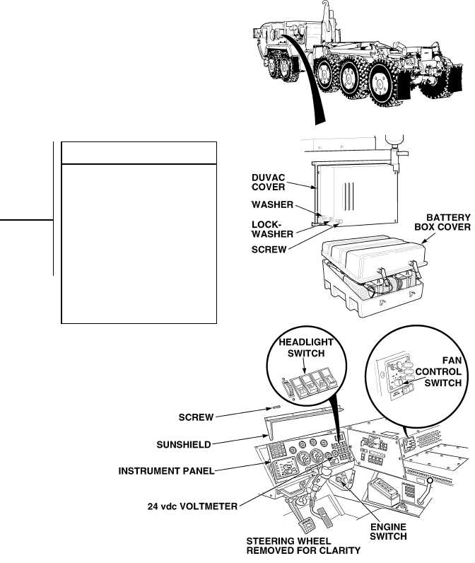
(1)   Start engine and turn on headlights and heater (TM 9-2320-364-10). (a)   If 26-28 vdc are not indicated on 24 vdc voltmeter, fault not corrected.  Perform Steps (2) through (5) below  and notify Supervisor. (b)   If 26-28 vdc are indicated on 24 vdc voltmeter, fault has been corrected.  Perform Steps (2) through (5) below. (2)   Turn off heater, headlights and engine switch. (3)   Install battery box cover. (4)   Install DUVAC cover with four screws, lockwashers and washers. (5)   Install instrument panel, sunshield, and ten screws. VERIFY REPAIR NOTE DUVAC controller should reset to the 24 vdc charge mode approximately every 55-60 seconds.  Observe 24 vdc voltmeter for at least two minutes to allow the regulator timer to cycle.

Privacy Statement - Press Release - Copyright Information. - Contact Us - Support Integrated Publishing

Integrated Publishing, Inc. - A (SDVOSB) Service Disabled Veteran Owned Small Business