|
| |
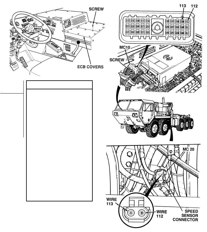
TM 9-2320-364-20-2
2-865
(1) Remove 15 screws and two
ECB covers.
(2) Loosen screw and disconnect
connector MC10 at ATEC ECU.
(3) Disconnect connector MC20 at
transmission speed sensor.
(4) Set multimeter select switch
to ohms.
(5) Is there continuity on wire 112
between connector MC20,
terminal B and harness connector
MC10, terminal 1L?
(a) If there is no continuity, repair
wire 112 (see schematic Fig 2-22)
or notify DS Maintenance.
(b) If there is continuity, wire 112
is OK.
(6) Is there continuity on wire 113
between connector MC20,
terminal A and harness connector
MC10, terminal 1M?
(a) If there is no continuity, repair
wire 113 (see schematic Fig 2-22)
or notify DS Maintenance.
(b) If there is continuity, wire 113
is OK.
(7) Connect connector MC10 to ATEC
ECU and tighten screw.
(8) Install two ECB covers and 15
screws.
CONTINUITY TEST
Remove all jewelry such as rings, dog tags, bracelets, etc. If jewelry or tools contact positive electrical
circuits, a direct short may result. Damage to equipment, injury or death to personnel may occur.
Circuit breakers CB5, CB6, CB12, CB20, CB22, CB23 and relays R3, R13 - R19, R26, R28, R32, R33 are
always electrically hot and can cause severe injury
|