|
| |
TM 9-2320-364-20-2
2-875
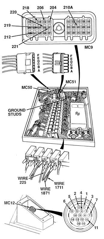
(1) Disconnect connectors MC50
and MC51.
(2) Loosen screw and disconnect
connector MC9 from ATEC ECU.
(3) Is there continuity on wire 210A
between connectors MC12,
terminal 1 and MC9, terminal 2C?
(a) If there is no continuity,
repair wire (see schematic
Fig 2-20) or notify DS
Maintenance.
(b) If there is continuity, wire 210A
is OK.
(4) Repeat Step (3) for terminals and
connectors listed in Table 2-27.
(5) Connect connector MC9 to ATEC
ECU and tighten screw.
CONTINUITY TEST
Remove all jewelry such as rings, dog tags,
bracelets, etc. If jewelry or tools contact
positive electrical circuits, a direct short
may result. Damage to equipment, injury or
death to personnel may occur.
Circuit breakers CB5, CB6, CB12, CB20, CB22,
CB23 and relays R3, R13 - R19, R26, R28, R32,
R33 are always electrically hot and can cause
severe injury to personnel. Care must be
exercised when working under the electrical
circuit board cover.
The following test checks continuity between
the terminals on connectors MC12 and the
other terminals on the ECB/ATEC wire harness.
Table 2-27 lists the terminal numbers on
connector MC12, the wire connected to them and
terminal at the other end of the harness.
Terminals on connector MC9 match those on
connector MC12.
Table 2-27. ECB/ATEC Wire Harness
Connector MC12 and MC9.
NOTE
MC12/MC9
Terminal
Wire
MC12/MC9
Terminal
Wire
1
2
3
4
210A
204
221
206
5
6
7
11
220
218
219
212
|