|
| |
TM 9-2320-364-20-3
2-2917
(1) Set multimeter select switch to ohms.
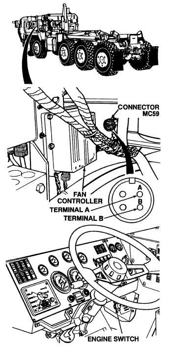
(2) START engine (TM 9-2320-364-10).
Do not increase engine rpm over idle.
(3) Measure resistance between
connector MC59, terminals A and B.
(a) If resistance is not within range
in Table 2-58, perform
Steps (4) and (5) below and
replace temperature sensor
(Para 7-65).
(b) If resistance is within range
in Table 2-58, temperature
sensor is OK.
(4) Turn OFF ENGINE switch.
(5) Connect connector MC59 to fan
controller.
RESISTANCE TEST
Remove all jewelry such as rings, dog tags, bracelets, etc. If jewelry or tools contact positive electrical
circuits, a direct short may result. Damage to equipment,
Table 2-58. Water Temperature Sensor Resistance
TEMPERATURE vs RESISTANCE CALIBRATION POINTS
Temperature
Resistance
(ohms)
Temperature
–40C (–40F)
–30C (–22F)
–20C (–4F)
–10C (14F)
0C (32F)
10C (50F)
20C (68F)
30C (86F)
40C (104F)
50C (122F)
684 30
728 30
774 30
821 30
870 30
921 30
973 30
1027 30
1083 30
1140 30
60C (140F)
70C (158F)
80C (176F)
90C (194F)
100C (212F)
110C (230F)
120C (248F)
130C (266F)
140C (284F)
150C (302F)
1199 30
1259 30
1322 30
1385 30
1451 30
1518 30
1587 30
1657 30
1729 30
1803 30
Resistance
(ohms)
|