|
| |
TM 9-2320-364-20-3
2-2043
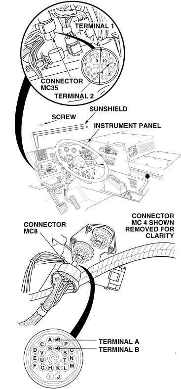
(1) Disconnect connector MC35 from
CTIS controller.
(2) Disconnect connector MC8 from
cab wiring harness.
(3) Set multimeter select switch to
ohms.
(4) Is there continuity between
connector MC35, terminal 1 and
connector MC8, terminal A?
(a) If there is no continuity,
repair wire 1519 (see sche-
matic Fig 2-48) or notify DS
Maintenance.
(b) If there is continuity, go to
Step (5) below.
(5) Is there continuity between
connector MC35, terminal 2 and
connector MC8, terminal B?
(a) If there is no continuity,
repair wire 1519 (see sche-
matic Fig 2-48) or notify DS
Maintenance.
(b) If there is continuity, replace
CTIS controller (Para 13-7),
then perform Steps (6)
through (8) below.
(6) Connect connector MC8 on cab
wiring harness.
(7) Connect connector MC35 on CTIS
controller.
(8) Install instrument panel and sun-
shield with ten screws.
CONTINUITY TEST
Remove all jewelry such as rings, dog tags, bracelets, etc. If jewelry or tools contact positive electrical
circuits, a direct short may result. Damage to equipment, injury or death to personnel may occur.
|