|
| |
TM 9-2320-364-20-3
2-2175
(1) Set multimeter select switch to vdc.
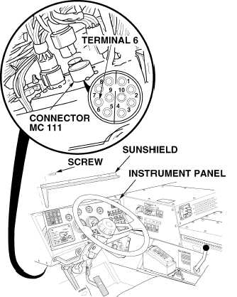
(2) Insert positive (+) multimeter lead, with
long probe installed, at back of
connector MC 111, terminal 6.
(3) Connect negative (–) multimeter lead to
front manifold ground braid.
(4) Turn ON ENGINE switch
(TM 9-2320-364-10).
(a) If 4.7 to 5.2 vdc are not present, turn
OFF ENGINE switch and replace
CTIS controller (Para 13-7).
(b) If 4.7 to 5.2 vdc are present, turn
OFF ENGINE switch and go to
Step 5 of this Fault.
(5) Install instrument panel, sunshield
and ten screws.
VOLTAGE TEST
Remove all jewelry such as rings, dog tags, bracelets, etc. If jewelry or tools contact positive electrical
circuits, a direct short may result. Damage to equipment, injury or death to personnel may occur.
|