|
| |
TM 9-2320-364-20-3
2-2413
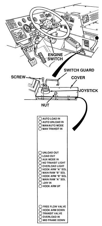
(1) Remove eight screws, switch guard
and eight nuts from LHS control
assembly.
(2) Carefully lift off LHS control assembly
cover. Do not allow cover to dangle by
joystick connecting wires.
(3) Turn ON ENGINE switch
(TM 9-2320-364-10).
(4) Set hydraulic selector switch to MAN
MF position.
(5) Hold joystick in UNLOAD position.
(6) Observe red indicator lights in bottom
of LHS control assembly.
(a) If MAIN RAM A indicator
lamp does not illuminate with
joystick in UNLOAD position
replace LHS control assembly
(Para 7-40).
(b) If MAIN RAM A indicator
lamp does illuminate, LHS control
assembly is OK.
(7) Turn OFF ENGINE switch.
(8) Set hydraulic selector switch to OFF
position.
VISUAL INSPECTION
Remove all jewelry such as rings, dog tags, bracelets, etc. If jewelry or tools contact positive electrical
circuits, a direct short may result. Damage to equipment, injury or death to personnel may occur.
Do not allow the LHS control box assembly
cover to hang from console by the wire
connections to the control box assembly.
Failure to comply will damage the wire
connections.
|